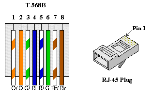
Ethernet Pinout Diagram
View Ethernet Pinout Diagram Pictures. Please be aware that modifying ethernet cables improperly may cause loss of network connectivity. The following are the pinouts for the rj45 connectors.

Rj45 exists at the end of the ethernet cables that is used for internetwork communication.
This reduces the number of available it is on pin 9 on the ethernet board because pin 13 is used as part of the spi connection. Pins 10, 11, 12 and 13 are reserved for interfacing with the ethernet module and should not be used otherwise. Rj45 connector (jack/receptacle) pin numbering. If you need to repair a cable or provide connectors for utp cable, wire straight through (mdi cable shown)
0 Response to "Ethernet Pinout Diagram"
Post a Comment